
Background:
SPI was originally developed by Motorola, who are now known as Freescale, which NXP has bought out. SPI’s purpose was to have serial communication between host processor and peripherals.
- SPI works in Master Slave configuration. However, you can also connect 2 Masters via SPI.
- Slave does what is told to do only.
- Single Master and multiple Slaves.
- Synchronous. i.e. common clock.
- It uses 4 wires: send, receive, clock and select + Common ground.
Outline:
- Advantages/Disadvantages.
- When to use it.
- How to use SPI.
- Master and multiple Slaves configuration.
- Conclusion.
Advantages/Disadvantages of SPI:
Pros:
- Fast and easy.
- Fast for point-to-point connections.
- Easily allows constant data inflow.
- No addressing required – simple to implement
- Widely supported.
Cons:
- Slave Select lines (SS) makes multiple slaves very complicated.
- No acknowledgement ability.
- No inherent arbitration.
- No flow control.
When to use SPI:
It is used in small distances only. For instance, between devices in one PCB board or when communicating with an SD card. As you know from above paragraph, it needs to send clock signal with data. Sending the clock needs a lot of energy, PLUS, there will be a huge RC time constant for the wires when driving them for long distance. This is the main reason it is only used for short distances.
It is mostly used with simple peripherals. E.g. ADCs, serial LCDs and sensors.
How to use SPI:
It transmits the clock with data, and that what makes it much faster than UART, as the Slave does not need to know when data is ready. So, at clock tick, Slave picks up data and, therefore, data must be ready at this point (this must be ensured by the Master device).
- SCLK: Serial clock.
- CS: Chip Select lines.
- SDI: Serial Data In (on rising edge of clock).
- SDO: Serial Data Out (on falling edge of clock).
The clock normally operates normally in the range 1 to 2 MHz.
Number of slaves that can be driven depends on number of CS lines available.
Master view:
Slave view:
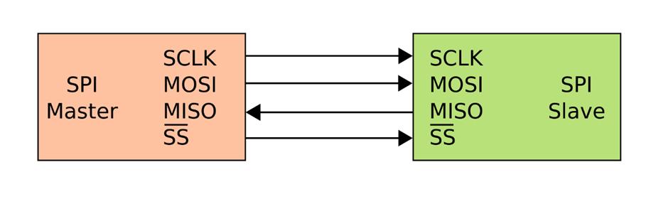
Wires:
- MOSI: Master out Slave in
- MISO: Mater in Slave out
- SCLK: System Clock
- SS_BAR: Slave Select 1..N
Operation:
- Master sets Slave to low (to activate it so it knows that the communication is done with it).
- Master generates the clock.
- Shift registers shift data in and out.
Shifting Protocol:
Master shifts out/in data to/from Slave.
Therefore, after 8 clock tick, all the data in Master have been shifted to Slave; and every thing in the Slave to the Master. Therefore, at every clock tick, Master and Slave shift out data and you cannot control this. If you do not want the received data to be stores, you simply ignore it.
Data must be shifted in/out Master AND Slave at every clock tick.
In a more detailed view, SPI looks like:
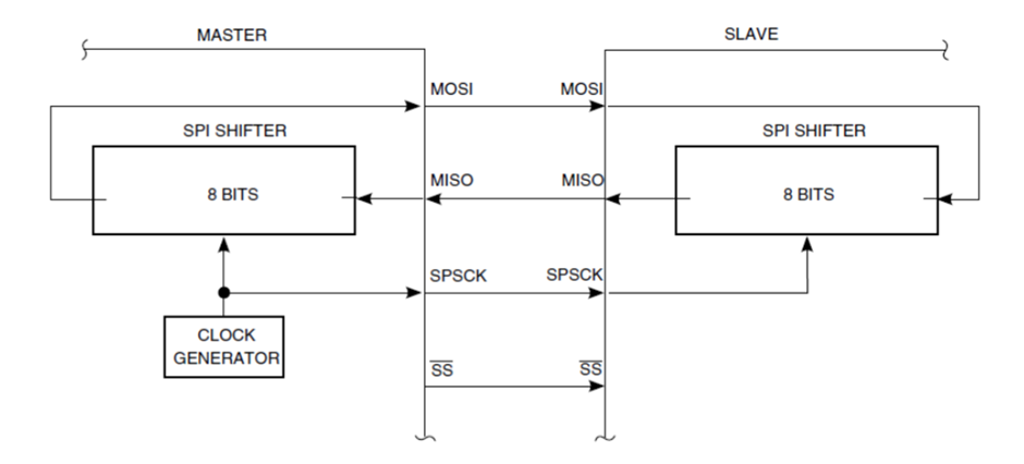
And that is for sure just same as what we have had before but it shows the shift register to reinforce the fact that data must be shifted in/out both devices at each clock tick.
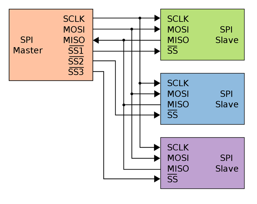
Master and multiple Slaves configuration in SPI:
It is as easy as connecting each Slave to the MOSI, MISO, SCLK and one of the SS_BAR lines.
However, there is another way to it:
By only connecting MOSI to the first Slave and then chaining the other Slaves with each other using MISO (Slave) to MOSI (Slave). We will be able to connect them using less wires. However, it will be slower as after 8 clock tick, Master only gets the register content of the last Slave and not the selected one.
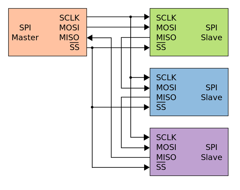
After 8 clock tick:
- Master data shifted to Slave 1
- Slave 1 to Slave 2
- Slave 2 to Slave 3
- Slave 3 to Master
This is used in, for example, LED strips. Each group of LEDs send data to the next group in the same strip.
Conclusion:
- SPI works in Master Slave configuration. However, you can also connect 2 Masters via SPI.
- Slave does what is told to do only.
- Single Master and multiple Slaves.
- Synchronous. i.e. common clock.
- Fast and easy.
- No addressing required – simple to implement.
- Widely supported.
- Number of slaves that can be driven depends on number of Chip Select lines (CS) available.
- Data must be shifted in/out Master AND Slave at every clock tick.